Finite Element Stress Analysis of Icosahedron Beam
by Ross Engineering, Prepared for: Mr. Sam Lanahan, Flextegrity
 Abstract
This is a stress analysis report for the Icosahedron Beam. The analysis was performed to compare a beam constructed of the Icosahedrons fabricated of Aluminum to a standard Wood beam. The predicted deflections are similar, while the component stresses in the Icosahedron beam are generally low. The finite element analyses were performed using Cosmos/M from Structural Research Analysis Corporation.
Objective
This simulation was performed to compare the deflections in the proposed icosahedron beam to that of a solid wood beam of the same nominal dimensions. The geometry provided was scaled to approximately 92% in order to approximate the net dimensions of a nominal 4″ x 6″ beam (3.5″ x 5.5″). This resulted in a beam with a 3.5″ x 5.58″ cross section.
Loading – Applied Load – The applied load of 250 lbf/ft is a round number (1000 lbf/4 ft) which produces a bending deflection near 1/360th of the span for the wooden beam around one axis. The maximum deflection of 1/360th of the span is a common design value for beams in the building trades. The same load was applied to both beams in both directions to make comparison easier.
Definitions:
Strong Axis – Parallel to the larger moment of inertia of the wood beam. This corresponds to the larger (5.58″) beam dimension.
Weak Axis – Perpendicular to the Strong Axis.
Von Mises Stress – Common name for one Total Energy theory (Maximum Distortion Energy). Materials generally fail in shear, but the standard test method is a tensile test. Using Von Mises stress allows the calculated stress to be compared with the measured (tested) tensile yield stress for a material.
Summary & Conclusions:
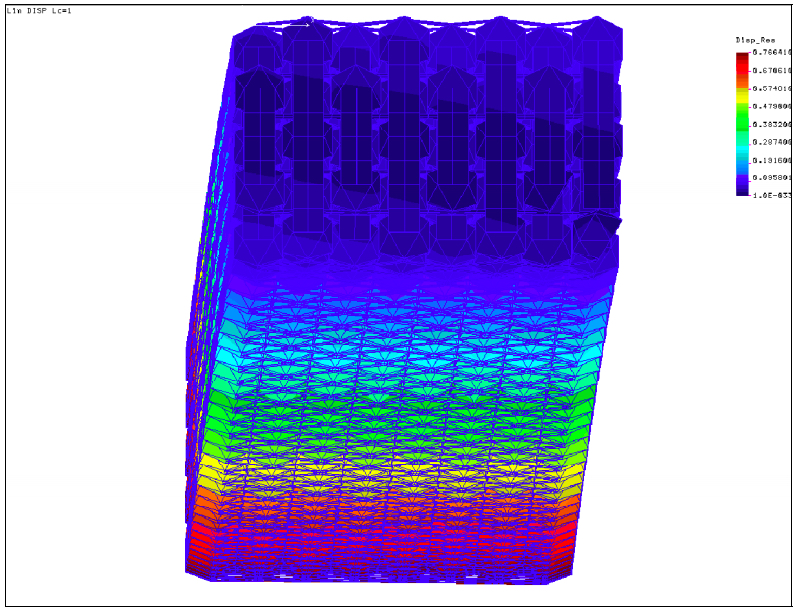
The predicted stress in the beam during weak axis bending locally exceed yield. This would cause local yielding and load redistribution in use, but is at least partly due to the method of load application. In strong axis bending, where the load had a larger area to be applied, the predicted stress is everywhere less than yield.
The predicted deflections were similar to the nominal wood beam. Predicted deflections were 0.493 in.(case 1) & 0.757 in. (case 2) vs. 0.64 in – weak axis and 0.079 in. vs. 0.25 in. – strong axis for the modeled and wooden beams respectively.
Assumptions
The analysis was performed using a shell surface model that represents the mid-plane of the part.
Only one half of the total length of the beam was modeled and symmetry at the center of the span was used. No other symmetry was used in modeling the beam because there were no other symmetry axes available.
The use of symmetry in analysis is common and is used to make a model a more manageable size. Symmetry is dependent on both part geometry and loading conditions. For this geometry and loading, the only axis of symmetry was located at the center of the beam.
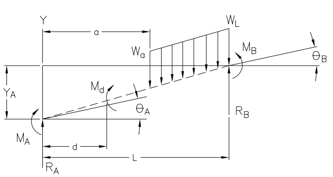
The symmetry boundary conditions applied at the beam center cause a moment to be applied at the beam center. This beam configuration is classified as simply supported and guided. As stated above, the beam length is one half of the simply supported beam or 4 feet. Comparing the closed form solutions for a simply supported beam and a simple-guided beam of 1/2 the simply supported beams’ length, it will be seen that the calculated deflections for the two cases are the same.


Figures 1 and 2 show the general notation and the specific beam supports used in the beam analysis. For the cases evaluated in this report, wa = wL and a = 0 and we thus have a uniform load on the entire span. The deflection equations for the two cases are shown below and the calculated deflections are compared.
For a simply supported beam with a uniform load, the deflection may be found from:
And for a simple-guided beam, the deflection may be found from:
Both beams have the same cross-section properties and Modulus of Elasticity. The simple-guided beam is one half the length of the simply supported beam and
,therefore, the deflections for the half symmetric beam and the simply supported beam will be
the same for beams given the same cross section and material and the assumption of
symmetry is valid.
Discussion of Analysis Details
To read the full Analysis & engineering report, please refer to Stress Analysis of Icosahedron Beam pdf here >>>
References:
Machinery’s Handbook, Erik Oberg, Franklin D. Jones, and Holbrook L. Horton, 23rd Edition, Industrial Press Inc., New York, 1988
Mark’s Handbook for Mechanical Engineers, 8th Edition, McGraw-Hill, 1989.
Mechanical Engineering Design, Joseph E. Shigley and Charles R. Mischke, Fifth Edition, McGraw-Hill Book Company, 1989
Roark’s Formulas for Stress and Strain, Warren C. Young, Sixth Edition, McGraw-Hill Book Company, 1989
Uniform Building Code, International Conference of Building Officials, 1991 Edition
Engineering Data for Aluminum Structures, The Aluminum Association, Inc., Fifth Edition, 1986
Specifications for Aluminum Structures, The Aluminum Association, Inc. Fifth Edition, 1986


 Abstract

