by Mark A. Martin, Ph.D. August 2006, © Flextegrity, Inc. 2006, 2007
Introduction
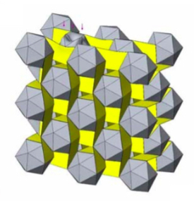
An icosahedral material is a regular threedimensional array of icosahedra held together by a repeating pattern of flexible interconnecting bands. Each interconnecting band attaches to exactly two icosahedra and each icosahedron has up to 12 bands attached to it, depending on its position within the material. For interior icosahedra with 12 attached bands, this restrains motions in both directions for all three Cartesian coordinate axes. The approach to understanding the motions of an icosahedral material that I will follow in this document is to assume that the icosahedra are rigid bodies and apply Newtonian physics to describe their motions. I will begin by considering the motions of an icosahedron in the material in response to changes in the positions of its attached interconnecting elements and any forces applied to it. Once I have determined the equations that describe these motions, it will then be possible to describe the motions of the entire material by considering interconnected arrays of icosahedra whose individual motions alter the positions of the ends of the interconnecting elements that are attached to their neighbors. The resulting mathematical model will allow investigation of the behaviors of a material in static or dynamic contexts. Solving the equations of the model, which means constructing approximate solutions on a computer, will be easier in the static case but may require significant computational power and skill in both cases.
For the purposes of constructing a tractable mathematical model, I will assume that an icosahedron is a rigid shell of material between two concentric icosahedral surfaces with constant density ρ and uniform thickness T, as measured, for example, at the center of a face. So I am ignoring any additional structure in the interiors of the icosahedra, either assuming that any such structures have too little mass to be important or that the mass of any interior bracing is also icosahedrally distributed.
In general, an icosahedron within an icosahedral material may experience the following forces:
- the force of gravity,
- other body forces such as electromagnetic interactions due to a charge
distribution within the shell, - forces on any exterior surfaces of the form
, where
and
are coordinates of points on the surface and t is the time,
- forces due to the motions of the interconnecting elements attached to the icosahedron.
Surface forces include externally applied forces and possibly forces generated when icosahedra collide. If the faces of the icosahedra are frictionless, then only the components of surface forces on the exteriors of icosahedra that are normal to the faces will influence the icosahedra. If, however, the faces exhibit friction, then tangential components will also have effects. The last two forces will usually change over time. The force of gravity will be assumed to remain constant and may or may not be important in a given situation.
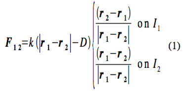
Interconnecting elements could be represented as hinges, linear springs with or without a failure point, or elastic bands that attach to points on the faces, edges, or vertices of the icosahedra. In hopes of realistically representing the interconnecting elements in the simplest way possible, I will assume that the interconnecting elements are linear springs that exert forces along the lines connecting the points where their ends attach to icosahedra and that the masses of the elements are small enough to be neglected. Suppose that I1 and I2 are icosahedra that are attached by an interconnecting element at points r1 and r2, where r1 lies on I1 and r2 lies on I2. Let D be the natural length of the element and k be its spring constant. Then, in accordance with Newton’s third law and Hooke’s law, the force that the element exerts will be
(This isn’t quite right. The force that an interconnecting element exerts also acts to restore its angles of attachment and a particular orientation of the icosahedra it connects relative to each other. It doesn’t just act to restore the length of the element. This effect depends on whether a portion of either icosahedron lies between the connection points.) It might also be useful to allow the interconnecting elements to have different stiffnesses depending on whether they are stretched beyond their natural length or compressed shorter than their natural length. In this case,
Furthermore, it’s possible to specify that the interconnecting element breaks if stretched
too far. In this situation,
where Le>D is the length at which the interconnecting element breaks under extension and tb is the time of breakage. This description neglects any change in the properties of the element that might occur near the breaking point and neglects any recoil that might occur afterwards. An analogous condition may be imposed if the element breaks when compressed too far. Notice that, under the above description and consistent with Newton’s third law, the force that a connection exerts on the second icosahedron is simply the opposite of the force that it exerts on the first icosahedron.
Theory of Elasticity References:
Feynman, Leighton, and Sands V. II, pp. 381 to 3913 and pp. 316 to 3112; Borisenko and Tarapov, pp. 668 and 702; Strang pp. 15581; Fetter and Walecka pp. 45979; and Arfken pp. 14050.
Equations of Motion for a Rigid Body
The motions of a rigid body are completely specified by Newton’s second law
which states that the force F is the rate of change of the (linear) momentum p, and its rotational counterpart
which states that the torque N is the rate of change of the angular momentum L. Here m is the mass of the body and a is its acceleration. Any quantities written in a bold font or, alternatively, with arrows over them are vector quantities.
In analyzing the motions of a body, it’s worthwhile to consider three different coordinate systems, as shown in Figure 1. In this discussion, I will adopt the notation of Fetter and Walecka. (For information related to the following analysis, see Fetter and Walecka pp. 1349 and pp. 319; Fowles pp.11722 and Chapters 7 and 8; and Bourg Chapters 1, 14, and 15.)
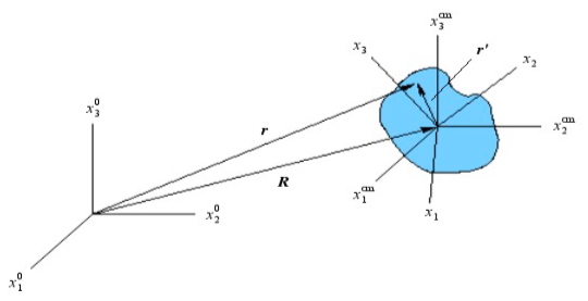
I will first introduce a coordinate system associated with the perspective of an inertial observer, typically located outside of the body, who is watching the body move. This coordinate system is a righthanded Cartesian coordinate system with coordinates
and corresponding unit basis vectors
where i=1, 2,3. I will call this frame the “primary inertial reference frame” or simply “primary frame.” This is the coordinate system from which we’d like to determine the body’s motions. I define the vector R to be the position of the center of mass of the body
in the primary frame. The center of mass of an icosahedron lies at the center of the icosahedron. So, in this case, R points from the origin of the primary frame to the center of the icosahedron.
The other two coordinate systems are associated with the body itself and are used to simplify the analysis. The first of these is a coordinate system that has the same unit basis vectors as the primary frame with its origin located at the center of mass of the
body. I will call this frame the centerofmass frame. Its coordinates will be
where
The third coordinate system is a righthanded Cartesian coordinate system with its origin
at the center of mass of the body that is attached to the body and fixed so that it moves as
the body moves. I will call this frame the body frame and define
to be its coordinates and
to be the corresponding unit basis vectors, where again i=1, 2,3. The position r of an arbitrary point in the body as seen from the primary frame may be written as
r = R+r ‘,
where r‘ is the position of the point relative to the center of mass at R. For each point in the body, the position r‘ relative to the center of mass is fixed in the body frame and only depends on the particular point chosen.
The center of mass moves like a point mass, having the mass M of the entire body, that experiences the net force Ftotal applied to the body. Therefore, the position of the center of mass R satisfies Newton’s second law
where L‘ is the angular momentum of the body about the center of mass. The rotational analog of Newton’s second law allows us to calculate how L‘ changes in response to the applied forces. It implies that
where Ntotal is the net torque. The angular momentum L’ may be expressed in terms of the moment of inertia tensor I and the angular velocity as
so that Equation (9) may be rewritten as
This equation determines the angular velocity of the body as a function of time. The components of the moment of inertia tensor are constant in any particular body frame and are given by
for i , j=1,2, 3, where is the density of the body,
is the Kronecker delta, and the integration ranges over all points P in the body, where
are the components of P in the chosen body frame. (See Feynman, Leighton, and Sands V. II, pp. 316 to 318; Fetter and Walecka pp. 1347; and Fowles pp. 2179.) Notice that the moment of inertia tensor is symmetric, which means that its determination only requires the evaluation of 6 of these integrals rather than all 9.
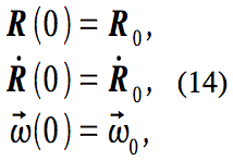
Given specified primary and body frames, Equations (7) and (9) provide the equations of motion for the body
where r=R+r‘ . These equations are usually coupled since the force usually depends on the position of the body. Aside from these equations, it is also necessary to specify the initial conditions
where and
0 are constant vectors, as well as the forces
F = F ( r, t ) (15)
that the body will experience. In addition, the motions of the body may be constrained in some way. Any such constraints must be consistent with the initial conditions. System (13) with the initial conditions given in System (14), possibly some constraints, and specified forces provide 6 scalar differential equations that determine R and and completely determine the motions of the body.
When working with these equations, it is important to be careful to express vector components in the appropriate coordinate systems. In any single equation, the components of all terms must be expressed in the same coordinates when solving the
equation. The equation for the position R of the center of mass is best solved in the primary frame and the equation for the angular velocity is best solved in the body frame. Therefore, it is important to be able to express the angular velocity in the centerofmass frame and the torques in the body frame. Translating back and forth between the primary and centerofmass coordinate systems is a straightforward matter of adding or subtracting R to or from the position. But the transformation between the body and centerofmass coordinates is complicated and timedependent, and it is necessary to solve an additional system of differential equations to determine it.
To find this coordinate transformation, consider the unit basis vectors for the body frame. These vectors may be expressed in the centerofmass frame as
where i=1, 2,3 and
If are the components of the angular velocity
in the body frame, then the angularvelocity in the centerofmass frame is
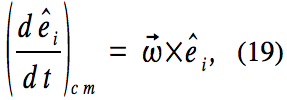
Since the unit basis vectors for the body frame do not change in the body frame,
for all i. This equation provides 9 differential equations that determine the coefficients for i , j=1,2, 3 and describe the rotation of the body frame in the center of mass frame given the initial positions of the body frame unit vectors in the centerofmass frame
Since these equations contain the angular velocity, they are coupled with the equations of motion and must be solved simultaneously with the previous equations. This approach requires solving 15 scalar differential equations to determine the motions of a rigid body and, in particular, of each icosahedron.
Rather than using the coefficients to specify the rotation of the body coordinate system, it is possible to describe rotations using mathematical entities called quaternions, which can be thought of as a generalization of complex numbers. (See Kuipers, Bourg pp. 2279, Behnke et al pp. 46777, Penrose pp. 198208, and the Wikipedia (1,2,3) and Wolfram MathWorld entries pertaining to quaternions.) A rotation of angle
about an axis that points in the direction of the unit vector u is represented by the unit quaternion
In the center of mass coordinate frame, the quaternion that represents the rotation of the
body frame satisfies
where the angular velocity is written as the “pure” quaternion
In the body frame, q satisfies the equation
where is written in the body frame instead. The equations are different since quaternions do not commute under multiplication. The solution to either equation must satisfy the initial condition
where q0 is a constant quaternion expressed in the appropriate coordinate system. If a point with initial position r ‘0 in the body has been rotated according to a quaternion q, then its new position is
r ‘ = q r ‘0 q * , (26)
where q* is the conjugate
of q. Using quaternions reduces the number of equations required for determining the coordinate transformation from 9 to 4, which reduces the number of equations required for determining the motions of a rigid body and of an icosahedron, in particular, from 15 to 10.
Mathematical Representation of Icosahedral Shells
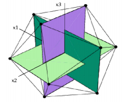
An icosahedron is conveniently represented in a righthanded Cartesian coordinate system that has its origin at the center of the icosahedron and has axes that pass through the centers of three perpendicular pairs of edges. (See the Wikipedia and Wolfram
MathWorld references related to the icosahedron.) For icosahedra, I define this to be the body coordinate system that I described above. Another way of looking at this is that the axes of the body coordinate system are the midlines of three perpendicular golden rectangles that define the icosahedron, as depicted in Figure 3.
An icosahedron with edges of length 2a has vertices of the form
in this coordinate system, where is the golden ratio =
. (See the Wikipedia and Wolfram MathWorld entries regarding the icosahedron and the Wikipedia entries regarding the golden ratio and golden rectangles.) The vertices may be categorized according to their zcomponents, as follows.
To read the full Report…
You can find the full model analysis & engineering report, in the Mathematical Model of Icosahedral Materials pdf here >>>


